Fine Environmental Services
Oxidiser Feeds
Organic waste guns are positioned at the top of the combustion chamber, with aqueous waste guns located slightly further down.
Fans are installed to provide an excess of air to the combustion process, ensuring that all organic species in the waste stream are completely oxidised.
Feed rates are continuously monitored and controlled to ensure that the required combustion conditions are satisfied and emission limits met.
Continuous balancing of waste streams is essential to avoid periods where too few calories are available within the wastes to maintain prescribed combustion conditions, with additional storage capacity proposed to ensure uninterrupted access for customers.
Combustion Process
 The regulatory requirement for combusting hazardous waste (as prescribed in the Hazardous Waste Incineration Directive (“HWID”)) is to thoroughly mix and maintain the temperature of the combustion mixture (waste, support fuel and air) at or above 850 °C in the case of waste streams containing less than 1% of organically bound chlorine, or above 1,100 °C for wastes containing more than this limit, for a minimum of 2 seconds.
These incineration conditions are considered critical to prevent the formation of highly toxic dioxins and furans in the off-gas.
The conditions in the combustion chamber are highly turbulent, with waste streams being atomised by compressed air before being ignited in a large volume air stream delivered by the fans.
Temperatures in this area exceed 1,400 °C, before aqueous waste (or tempering water) is atomised at the bottom of the chamber, reducing the temperature of the waste stream gases to either 850 °C or 1,100 °C, depending on the waste type.
The waste gases then exit the combustion chamber and are directed to the flue-gas treatment units.
The structural strength of the combustion chamber is provided by a steel shell, lined with a layer of insulating bricks and a layer of refractory bricks, the latter providing a measure of protection from the erosion which could occur under the highly aggressive, turbulent conditions.
Quench and Combustion Gas Treatment
 When the combustion gases exit the combustion chamber, they are rapidly quenched using water spray to reduce their temperature.
The possibility to retrofit equipment to recover heat from the flue gases is provided for within the design.
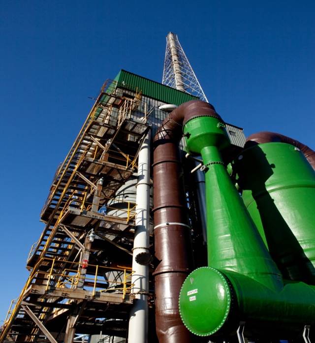
The combustion gases are directed into a venturi scrubber where they come into contact with a dilute solution of caustic soda in a packed column constructed from acid resistant materials.
This scrubbing system is designed to remove any Nitrogen oxide (“NOx”) and Sulphur oxide (“SOx”) acid gases present in the waste gas to within permitted limits.
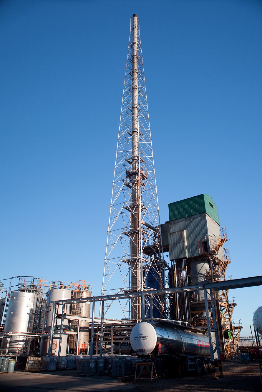
The scrubbed gases will then feed forward into a wet electrostatic precipitator (WESP) to ensure removal of particulate solids to within regulatory limits, and from there to a heat exchanger where the water saturated gases are heated to ensure no visible steam plume exits the top of the 90 metre high stack.
With provision of heat recovery comes a requirement to provide additional protection for destruction of dioxins and this will be provided in a DeNOx unit fitted after the WESP.
Monitoring and Control
Monitoring and emissions control of the plant are automated, with hard-wire trips in place to ensure compliance with all regulatory conditions.
The most important of these is the temperature condition monitoring in the combustion and steam generation systems and the continuous stack gas analysis to ensure compliance with emission limits.
Oxygen, carbon monoxide, nitrogen dioxide, nitrous oxide, water, hydrogen chloride, humidity, dust, gas volume and flue velocity are all continuously monitored and recorded with an MCERTS rated CEMS device.